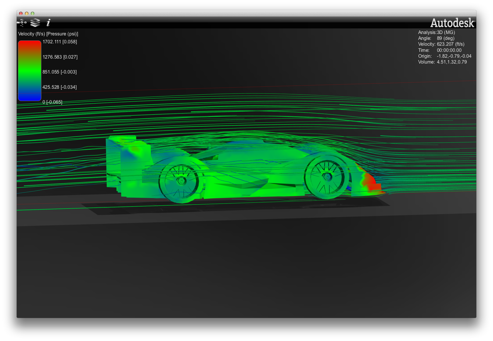
The Traxxas LMP model got to see some simulated wind tunnel time. Autodesk Labs has a lightweight CFD simulator available for a limited time. It'll take a 3DS or STL model and run computations in a fixed-ground tunnel environment. The results are perhaps not absolutely precise but for my purposes insightful enough.

The longer trailing bodywork tail is better at reducing the low-pressure area along the roof and rear cowl. A shallower front splitter trailing edge may be better as the extreme low pressure behind the steeper angle may be adding drag. The venting around the front cowl and aft of the front fenders appears to flow the front splitter very well. Vents just aft of the tops of the front fenders will reduce negative pressure inside the wheelwells.
Internal pressure buildup in front of the rear bulkhead and wing mount (the area behind the motor) suggested a dorsal vent would help vent the motor area, aiding in the cooling airflow and also helped reduce negative pressure over the rear part of the deck. Also, my pressure points at the splitter and underfloor are right where I want them. Coupled with the wing and bodywork, the system appears to function quite well.
